SIEMENS

Symaro™
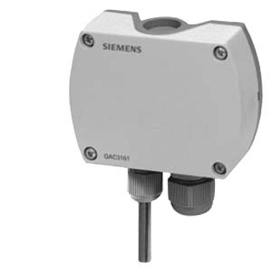
Outside Temperature Sensors•
Active sensors for acquiring the outside temperature•
Operating voltage AC 24 V or DC 13.5...35 V•
Signal output DC 0...10 V or 4...20 mAUseThe QAC31... outside temperature sensors are for use in heating, ventilation and air conditioning plants as:
• Reference sensors for outside temperature-compensated control
• Measuring sensors, e.g. for optimization, measured value indication, or for connection to a building automation and control system
• High-end sensors for acquiring the room temperature in commercial spaces
Type summary| Type reference | Measuring range | Operating voltage | Output signal |
| QAC3161 | -50...+50 °C | AC 24 V+20%/DC 13.5...35 V | DC 0...10 V |
| QAC3171 | -50...+50 °C | DC 13.5...35 V | 4...20 mA |
Ordering and deliveryWhen ordering, please give name and type reference, e.g.:
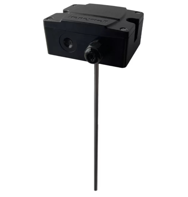
Outside temperature sensor
QAC3161.The sensor is supplied complete with cable entry gland M16.
Siemens Building Technologies
HVAC Products
Equipment combinations
All systems or devices capable of acquiring and handling the sensor's DC 0...10 V or 4...20 mA output signal.
The sensor acquires the outside temperature via its sensing element whose resistance value changes as a function of the temperature. This change is converted to a DC 0...10 V or 4...20 mA output signal, depending on the type of sensor. The output signal corresponds to the selected temperature range.
The outside temperature sensor consists of housing, printed circuit board, connection terminals and measuring probe.
The two-sectional housing is comprised of base and removable cover (screwed connection). The measuring circuit and the setting element are located on the printed circuit board inside the cover, the connection terminals on the base.
The measuring probe is screwed into the bottom of the housing.
Cable entry is either from the rear (concealed wiring) or from below (surface-run wires). For that purpose, a hole can be knocked out in the base or the enclosed cable entry gland M16 can be screwed into the bottom of the base.

The setting element is located inside the cover. It consists of 6 pins and a shorting plug. It is used to select the required measuring range and to activate the test function.
The different plug positions have the following meaning
• For the temperature measuring range:
Shorting plug in the left position (R1) = 0...50 °C
Shorting plug in the mid position (R2) = -50...+50 °C (factory setting)
Shorting plug in the right position (R3) = -35...+35 °C
• For activating the test function:
Shorting plug in the horizontal position: The values according to the table "Test function active" will be made available at the signal output.
In the event of fault, the output signal will reach 0 V (4 mA) after 60 seconds.
To power the sensor, a transformer for safety extra low-voltage (SELV) with separate windings for 100 % duty is required. When sizing and electrically protecting the transformer, local safety regulations must be observed.
When sizing the transformer, the power consumption of the outside temperature sensor must be taken into consideration. For correct wiring, refer to the Data Sheets of the devices with which the sensor is used.
The permissible cable lengths must be observed.
When laying the cables, it must be observed that the longer the cables run side by side and the smaller the distance between them, the greater the electrical interference. Twisted pair cables are required for the secondary supply lines and the signal lines.

| Mounting location | Depending on use, the outside temperature sensor must be located as follows:
• For control:
On the wall of the house or building that has the windows of the occupied rooms, but the sensor must not be exposed to the morning sun. In case of doubt, it should be mounted on the wall facing north or north-west
• For optimization:
Always on the coldest wall of the house or building (normally the wall facing north). The sensor must never be exposed to the morning sun |
| Mounting height | Preferably in the middle of the house or building or heating zone, but at least 2.5 m above the ground.
The sensor must not be fitted at the following locations:
• Above windows, doors, air exhausts or other heat sources
• Below balconies or the eave of the roof
To prevent measuring errors due to air circulation, the cable conduit at the sensor should be sealed.
The sensor may not be painted over.
Mounting Instructions are printed on the packaging. |
| Commissioning notes | Check wiring before switching on power. The temperature measuring range must be selected on the sensor, if required. |
Mounting notes
Technical data
| Environmental conditions | Operation
Climatic conditions
Temperature (housing with electronics) Humidity
Mechanical conditions | IEC 721-3-3
class 3K5
-40...+70 °C
5...95 % r. h. (non-condensing) class 3M2 |
| Transport
Climatic conditions Temperature Humidity
Mechanical conditions | IEC 721-3-2 class 2K3 -25...+70 °C <95 % r. h.
class 2M2 |
| Materials and colors | Base | polycarbonate, RAL 7001 (silver-grey) |
| Cover | polycarbonate, RAL 7035 (light-grey) |
| Measuring nipple | stainless steel 1.4401 |
| Cable entry gland | PA, RAL 7035 (light-grey) |
| Sensor (complete assembly) | silicone-free |
| Packaging | corrugated cardboard |
| Standards | Product safety Automatic electrical controls for household and similar use | EN 60 730-1 |
| Electromagnetic compatibility Immunity Emissions | EN 61 000-6-2
EN 61 000-6-3 |
| C€ conformity to | EMC Directive 89/336/EEC |
| G conformity to
Australian EMC Framework Radio Interference Emission Standard | Radio Communication Act 1992 AS/NZS 3548 |
| Weight | Incl. packaging QAC3161
QAC3171 | approx. 0.13 kg
approx. 0.13 kg |